Different circuit neeeded for automatic upload using CP210x #480
Comments
|
the problem is the Arduino IDE or you Serial terminal. is the boot loading still working with the 10k? the problem shut be fixed in software (Arduino IDE) so that DTR and RTS is not activate in our case. |
|
Yes 921600 is working fine for me. |
|
I thing I have the same problem here. What are your resistor values for "pull up and pull down"? |
|
10K |
|
What are u doing with GPIO0 and RESET when the CP210x is not connected? What values are you using in this case? |
|
Good point. In my case the CP210x is always connected and is also used to provide the 3.3V (which appears to work sometimes in my case - better use the 5V from USB and a voltage regulator). I guess you'd have to put in pullups instead when the CP210x is removed. |
|
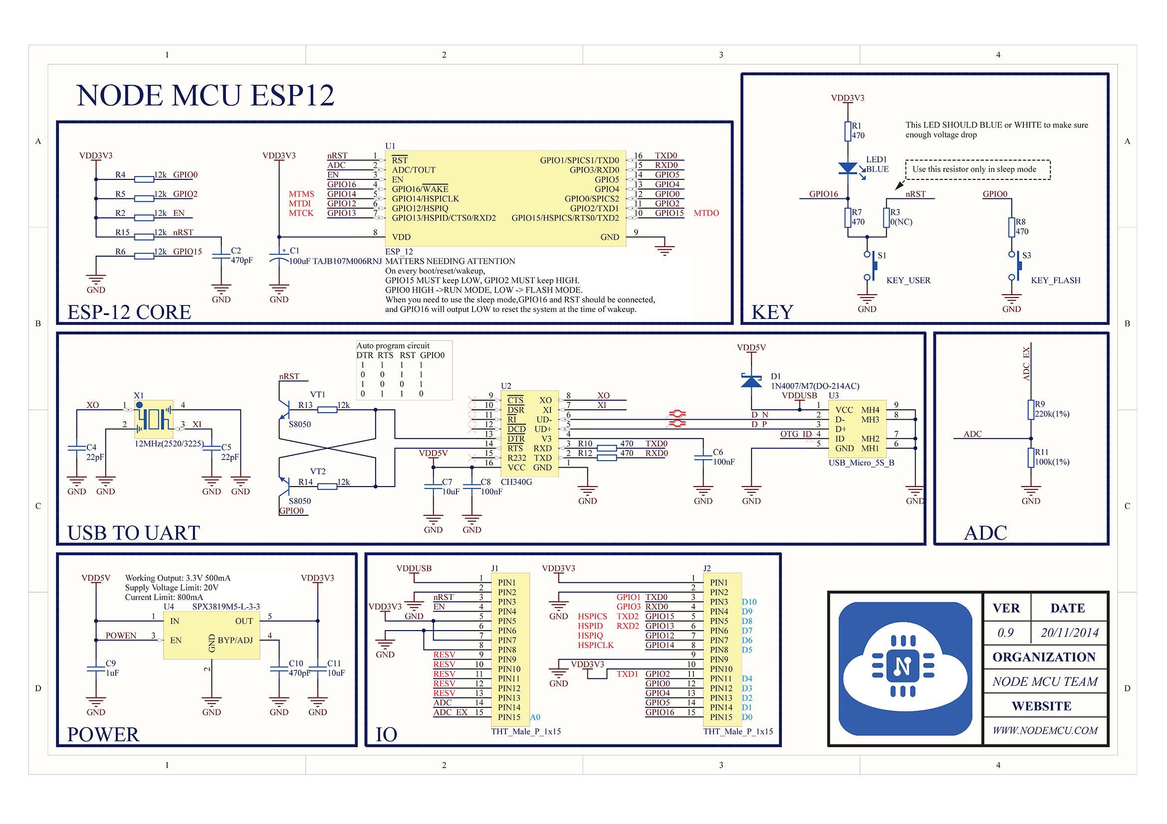
Following advice from igrr, I am now using the circuitry from the NodeMCU 0.9 for my ESP-12Es. See the schematics of the NodeMCU 0.9.
I used slightly different parts that I had lying around, two 2N2222 npn transistors and 3 10k resistors, thereof 1 pullup for CH_PD. (I think I inadvertently connected CH_PD instead of nRST; need to double check.) U2 is the CP210x in my case. Note that it cannot provide enough 3.3V current, but using a voltage regulator to convert 5V coming from USB works. Working well (occasionally I have to press upload twice, maybe this is related to me wiring up CH_PD instead of nRST). This circuit can be used for flashing and running, it does auto-reset and the serial monitor in the IDE can be used. I built a jig out of perfboard that holds the ESP-12E in place using the castellated pins.
This way I can flash and experiment with bare ESP-12E boards very quickly - no need to solder anything to them. Possibly the documentation in the README should be updated to reflect this. |


|
Thanks probonopd, This solved my issue aswell.For everyone who find it hard to read electronic schematics. I created a simplified example using a breadboard explanation. |
|
Thanks JeroenBeemster, I hope you are not offended if I attach your example for quick reference here.
|

|
I have tried several methods on resetting the ESP-12E for flashing with Arduino IDE Since i had a ATtiny85 lying around i used this to send the reset to the ESP:
I used a Arduino Nano with ArduinoISP sketch to program the ATTiny using IDE 1.6.5 Wire it up: Choose ATTiny85 Board at 8Mhz and flash the Bootloader Wires for Serial debugging |
|
@igrr @probonopd ... reading the README on the esptool github repository, and using pin nomenclature from the wiki, it says:
I believe CHIP_EN is synonymous with CH_PD (i.e. pin 7 of the ESP8266).. Looking at the whole NodeMCU 0.9 schematic, it would appear that they label this net "EN" and it is simply pulled up to 3.3V. They effectively connect the net named "nRST" which is synonymous with EXT_RSTB (i.e. pin 32 of the ESP8266), to the DTR line, and effectively connect GPIO0 to the RTS line. That's quite a difference to the recommendations of esptool. Unless RTS and DTR are functionally symmetric? They've also put a small capacitance (470pF) to GND on the EXT_RSTB pin, that may be critically important to the functionality of this circuit? GPIO0, GPIO2, and EXT_RSTB are also passively pulled up to 3.3V, and GPIO15 is passively pulled down to GND. The difference between CHIP_EN and EXT_RSTB is pretty subtle, so it probably doesn't matter (?) which one gets wiggled for auto-reset/upload support.. But I'm more doubtful where it comes to the differences between RTS and DTR. Is the circuitry in this thread above still sound, or should new hardware wire to RTS and DTR in agreement with the esptool recommendations? Maybe this could be covered in the wiki somehow? |
|
The circuit in this thread works with esptool-ck when reset method is set On Tue, Oct 20, 2015, 16:33 Victor Aprea [email protected] wrote:
|
|
@igrr interesting, didn't realize there was a difference. So does auto-reset not work for "Generic ESP8266 Module" selections, or is the same wiring applicable in that case? I'm asking because I'm designing in an ESP8266 module on a board right now and would like to have it be compatible with this project. |
|
For those who just have FTDI cable with only DTR and no RTS line, I'm using this one (FTDI 5V compatible) with great success on ESP12 and ESP07
Of course for this to work, don't forget pull down on GPIO15 (10K). If your FTDI is 3V3 don't try to power your board with it (use another source), lot's of FTDI onboard reg can't do 200mA needed sometimes by ESP |

|
After some investigation, it's better to reset with CH_PD |
|
This looks promosing ! |
|
@ReMiA00 |
|
I am using the nodemcu circuit and it works great for programing, but my module reboots when I open and close the serial monitor. Expected behavior ? My logic probe, says my adapter DTR and RTS are both high at rest and LOW when serial monitor is open ( same for putty ). Changes to neither Are these in stable IDE yet? EDIT: |
|
FYI, I am using 2n3904 transistors (have a bunch) with 10k base resistors, I have not bothered calculating proper resistor values yet.. Seems to work ok for programming every time so far. |
|
I had to come up with another circuit to do the "autoreset" with the FDTI interface as none of the above mentioned worked for me. I designed the PCB as an interface in between the FDTI an the board to be programmed, with an additional output of RESET and FLASH (GPIO0).
|

|
I tried JeroenBeemster's circuit on esp8266-01 and work very well. I tried the same on esp8266-12F but receive warning: espcomm_sync failed error: espcomm_open failed error: espcomm_upload_mem failed. The same with hallard's. Do you have suggestions for me? :-) |
|
Sorry I make a mistake to wiring esp8266-12F. |
|
Make sure you are using nodemcu reset mode not ck |
|
ReMiA00 many thanks for the attiny85 solution. It is working well for me. At first I got it to work on an atmega328 since I could easily debug/test there. I then went to the attiny85 and built a circuit between my FTDI and ESP8266, now it is even more fun to develop for the ESP8266. |
[Comment shortened in order not to confuse people -- see https://github.com//issues/480#issuecomment-122993574 for the recommended circuit]
I can reliably upload using baud rate 921600.
It would be good if others could test this setup too and if it works for everyone, it could be changed in the README.
The text was updated successfully, but these errors were encountered: