Tutorial for Airbus VS display via 7 Segment LED Module
This tutorial will walk through the process of displaying the V/S value from the FBW (FlyByWire) A32NX project's Airbus A320. Following this tutorial will demonstrate the usage of MobiFlight Preconditions and combining multiple values onto a single LED module.
The results will yield:

This will be accomplished by composing multiple MobiFlight data elements:
- Negation of the displayed value without moving the numerical data
- Small zeros in the tens and ones digits
- The appropriate "dashes" placeholder when V/S is managed
This tutorial assumes you already have a working MobiFlight installation and have gone through the Example 7 segment display example.
Hardware needed:
- 7 segment LED module
- A MobiFlight supported Ardunio
Software:
- Microsoft Flight Simulator 2020
- FlyByWire Simulators A32NX Mod
Here are the data elements we'll need to create our composite display. Each one will be explained in more detail in the Implementation section below. We're going to be placing different sources of data into specific LED characters within the same LED module.
| Logical Element | SimConnect Variable | Transform | Comparison Settings1 | Usage | LED Range | Precondition |
|---|---|---|---|---|---|---|
| V/S Rate | (L:A32NX_AUTOPILOT_VS_SELECTED) | Abs($/100) | Sim value for V/S | 2-3 | V/S is Managed = 0 | |
| V/S Rate (Dashes) | Literal '--' | Sim value for V/S | 2-3 | V/S is Managed = 1 | ||
| V/S Small Zeros | Literal 'oo' | Two lower case o's (not zeros) | 4-5 | V/S is Managed = 0 | ||
| V/S Small Zeros (Dashes) | Literal '--' | Placeholder when V/S is Managed | 4-5 | V/S is Managed = 1 | ||
| V/S Sign | Conditional literal '-' | Indicates when a V/S rate is negative | 1 | V/S is Managed = 0 | ||
| V/S Sign (Dashes) | Literal '-' | Placeholder when V/S is Managed | 1 | V/S is Managed = 1 | ||
| V/S is Managed | (L:A32NX_FCU_VS_MANAGED) | Indicates is the FCU is managing our V/S |
1The literal values must include the single quotes (e.g. '--') to prevent excessive error messages in the MobiFlight Connector console when debugging.
Important: We can't use a single instance of the dashes placeholder ('------') for all characters due to the behavior of MobiFlight preconditions. We need to have a value/placeholder pair for each range of LEDs (i.e. "V/S Rate" and "V/S Rate (Dashes)")
We'll walk through the initial setup process and a few item mappings.
First, we'll want to ensure we have the LED module configured. This can be accessed under the menu item Extras -> Settings, then click on the MobiFlight Modules. You should see that your Output is configured with the appropriate settings. In this example, we'll use the Name "VS Display".

Following the table above (Data Elements to be Used), create a new Mapping with the description "V/S Rate", using the SimConnect variable of "(L:A32NX_AUTOPILOT_VS_SELECTED)". Since the value is always represented in hundreds, we want to disregard the sim's tens and ones values by dividing the value by 100. Furthermore, we are going to manually provide our own sign value, since MobiFlight would shift the underlying values to the right in our display to accommodate the negative sign. Therefore, we'll include a transformation of Abs($/100).

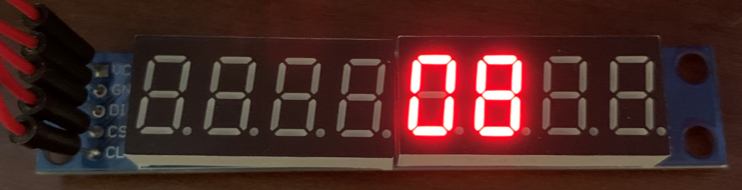
Now we specify the LCD module we previously created and map it to the appropriate LED Range, being sure to check "Use Left Padding" with the value of "0" (so a transformed value of 2, for example, would display as 02):

This is a good time to check that your display is functional, it displays the thousands and hundreds places, and does not display a negative sign at this point. It should look like this:
Now let's create a new Mapping with the description "V/S Sign". For this mapping, use the SimConnect "(L:A32NX_AUTOPILOT_VS_SELECTED)" once again. Under the Compare tab, display a negative sign if the value is less than zero, otherwise a blank string value of one space " " without the quotes. (You can see that there's a blank space entered into the "else set to" field directly before the cursor in the following screenshot)

Under the Display tab, specify digit 1 for the position.

You can now test that the negative sign appears appropriately in position one when changing your V/S Rate to a negative value within the sim.

This is an easy one. Create a new Mapping, "V/S Small Zeros", choose SimConnect as the Variable Type, but don't specify any variable, since we're going to show a literal value. Under the "Compare" tab, change the "Comparison Settings" to display 'oo' (two lower case o letters from the alphabet) if the "current value is" equal to zero (always true in this case).

Then go to the "Display" tab and specify the positions as 4 and 5:

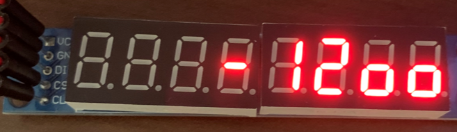
At this point you should see this when running the configuration and setting a negative V/S value within the sim:
Almost there! Now we want to replace the displayed values with dashes if the V/S is managed. NOTE: We cannot replace all the LED character positions at the same time. This must be done in a manner that "pairs" the managed and non-managed mode for each of the field groups: 1, 2-3, 4-5.
First, we create a Mapping to determine if V/S is managed. Create an Output Configuration "V/S is Managed", using the SimConnect variable of "(L:A32NX_FCU_VS_MANAGED)"

Now that we have this, you can use it to create preconditions (in pairs) to swap out each of the field groups with literal dashes in managed mode. We'll walk through this for one of the fields, V/S Rate (characters 2-3).
Edit the "V/S Rate" mapping, and add a precondition to only process the mapping when "V/S is Managed" is equal to 0:

Now we pair it with a literal '--' value (two dashes, since the field we're going to replace is two digits long). Create a new mapping, "V/S Rate (Dashes)", SimConnect type with no Variable specified, using the same "comparison" trick shown above (for the small zeros) to display two dashes:

Under the display tab, choose the same display fields to which we are "pairing" the value:

And then under the precondition tab, indicate this configuration is only evaluated when "V/S is Managed" is equal to 1:

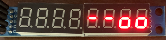
This is a good time to test that the V/S Rate field (digits 2-3) are correctly replaced with dashes when the V/S Rate is in managed mode:
Now, you'll need to repeat the previous logical steps (in the "Managed V/S" section) for all the other field groups: V/S Sign (character 1) and V/S Small Zeros (characters 4-5). Be careful that you choose the appropriate number of dashes to replace in your placeholder pair for each field group.
Once you've completed the process, you should have a V/S indicator that maps exactly to the sim, with the exception of the plus sign for positive climb rates (you can't display them on a normal 7-segment LED display).
Happy flying!
- MobiFlight Connector Installation
- Mobiflight Connector BETA version installation
- Modules
- MobiFlight Connector Files Structure
- MobiFlight Connector Uninstall
- Modules Reset to factory default
- Verifying the WASM module installation and locating the MSFS2020 community folder
- Verifying the WASM module installation and locating the MSFS2024 community folder
- Using a Winwing FCU with MobiFlight
- Using VKB controllers with MobiFlight
- Providing logs from MobiFlight
- MobiFlight Connector How does it work
- Mobiflight Connector Main Window
- Flash module with MobiFlight firmware
- Input and Output devices
- Joysticks
- Midi Boards
- Sim Variables (for Output)
- Input Actions
- Merging configuration files
- Disabling specific COM ports
- Examples Output LEDs
- Examples Input Switch
- Example 7 segment display
- Example Servo motor
- Controlling LEDs with an output shift register
- Adding lots of buttons with an input shift register
- Beginner's guide to input multiplexers
- Key Matrix with standard MobiFlight and Multiplexers
- Tutorial Easy Driver and x.27 or x.40 Stepper Motor
- Tutorial for Airbus VS display via 7-Segment LED Module
- Example Analog Input Potentiometer
- Baron G58 Tutorial Gear, Flaps, Mags, ELT Input Output Programming
- Using Mobiflight to control arduino-based 3rd party panels (RealSimGear GNS530)
- How to use a VNH2SP30 DC motor shield with MobiFlight
- Using 3D printer mainboards
- Playing sounds by sending keystrokes to AutoHotKey
- Using the selector knob on a Honeycomb Bravo
- Using an adjustable 12 position switch as a GA starter
- Brightness of LCD displays with I2C
- Using three-position switches
- Transponder with one Rotary
- Workflow for Creating Flight Simulation Panels ‐ Part 1
- MSFS2020 RPN Tips and Tricks
- MSFS2020 Using the Custom Input Code Box
- MSFS2020 Install WASM module and Event List
- MSFS2020 How to Create and Use User Defined Lvars
- MSFS2020 How to Create a Blinking LED configuration
- MSFS2020 User Defined WASM Module Events Best Practices
- MSFS2020 Developer Mode, Model Behavior dialog and Console window
- MSFS2020 PMDG 737‐700 List of Events that require use of FSUIPC7
-
MSFS2020 PMDG 737‐700 Calibrate throttle idle and reverse thrust using interpolation (Valkyrie)
- MSFS2020 PMDG 737-700 Chrono unit functions implemented in Mobiflight
- Configuring PMDG 737 Parking Brake Lever Auto-Release with a Servo in Mobiflight
- Using encoder to drive a value back and forth within a given range
- Adding a custom board to MobiFlight
- User guide - Community Board and Custom Devices
- Developing your own custom devices/boards